Axes and scales
Step 1 of setup. Nothing here moves the machine.
Use case
Set the use case to lathe. That is what exposes ELS mode at all — asking for a mode the use case does not allow silently falls back to DRO rather than half-starting one, so a machine set to the wrong use case looks like a machine whose ELS is missing.
Axis roles
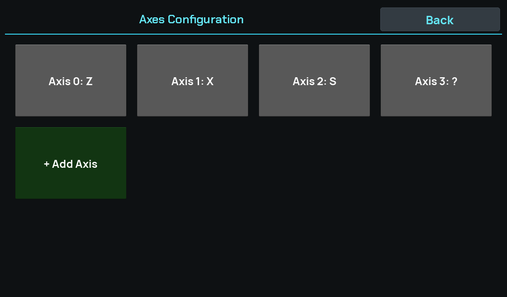
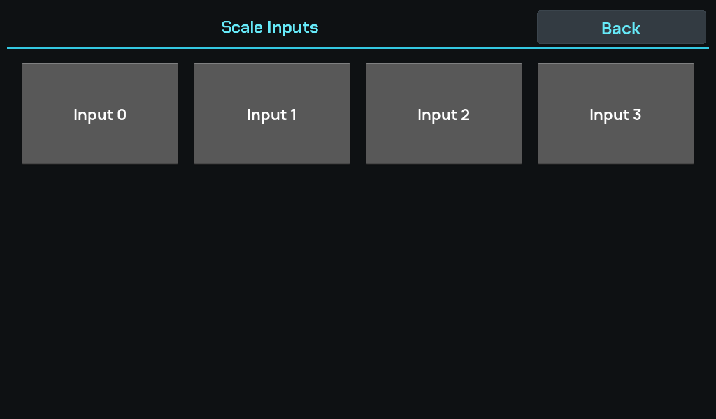
Name your axes and point each at a scale input under Axes, and give each input its resolution under Inputs:
Then set the ELS axis roles: which axis is Z (the saddle), which is X (the cross slide), and which is the spindle.
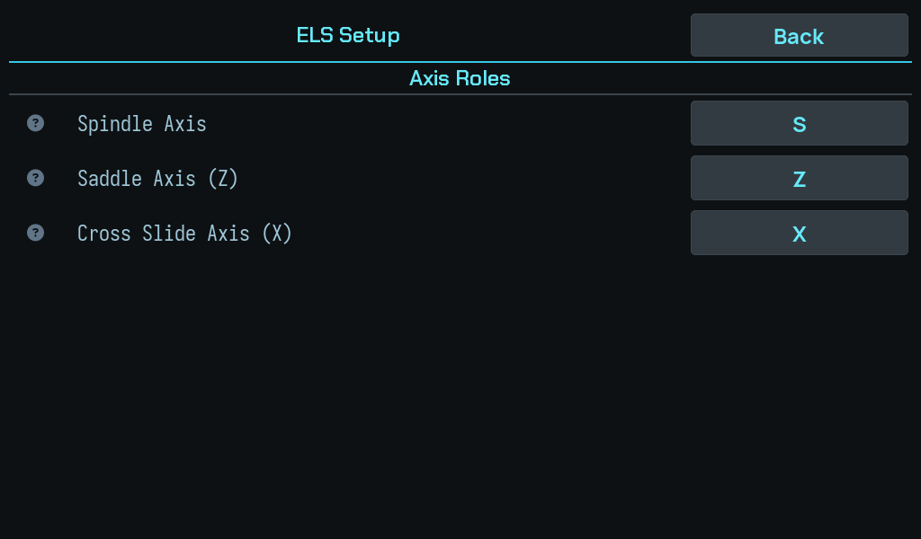
These are roles, not names. Calling an axis Z does not make the ELS use it —
the roles are a separate setting, and until they are assigned the ELS refuses
anything that needs them:
No ELS Z axis assigned — map it in ELS settings
The fourth axis named ?
The board carries four scale inputs and creates one axis per input, so a
machine using three of them still carries a fourth axis called ?.
That is correct and harmless. The input exists and may be wired later; deleting the axis to tidy up would throw away a real port.
An unnamed axis is not offered as a summed contributor
? is the marker for not provisioned yet. You can assign an input to such
an axis — that is how it gets provisioned — but it will not be offered as
the second contributor to another axis's Sum transform.
The reason is specific: a summed axis displays scale[a] + scale[b], but
the ELS is told a single scale index and tracks scale[a] alone. Summing in
a placeholder that reads zero forever would put a number on screen the
machine is not following. The ELS refuses to engage against a Z axis derived
from more than one scale for the same reason.
Scale resolution
For each input, set the resolution so the DRO reads true.
Verify it against a dial indicator over a decent travel rather than trusting the label on the scale. A label error and a wrong ratio look identical on screen: both give a readout that moves smoothly and reads plausibly, and they differ only by a factor you will notice at the part.
A long travel makes the error obvious — over half an inch, a 5% error is 0.025 in, which no dial indicator will hide.
Direction is part of the calibration
A scale reading the right magnitude in the wrong direction produces a take-up that moves the carriage the wrong way, which the controller catches and calls out specifically:
Cut aborted — WRONG-way motion. Check the Z scale direction.
Better to find it here with a dial indicator than at the first pass.
Next: Servo and leadscrew.