Servo and leadscrew
Step 2 of setup. Nothing here moves the machine, and getting it wrong is the least visible mistake in the whole system.
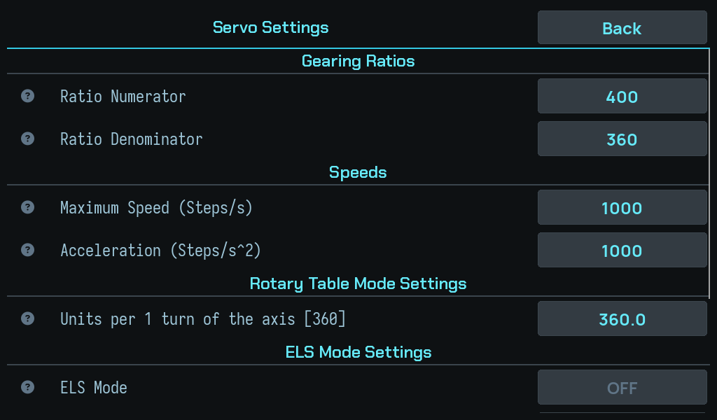
What you are setting
Three numbers that together convert a distance into leadscrew steps:
- the leadscrew pitch — how far the carriage travels per leadscrew turn;
- the servo steps per revolution — including any microstepping;
- the gearing between the servo and the leadscrew, if they are not direct.
Why a mistake here hides
The DRO reads from the scales, which are independent of all three. So a wrong servo ratio produces a machine where:
- the position on screen is correct,
- the readout tracks smoothly and plausibly,
- and every commanded move is wrong by the ratio.
There is no symptom on the display. The stop still fires at the right place — the stop is enforced against the Z scale — so even threading to a shoulder looks right. What is wrong is the size of every motion the controller generates: the backlash take-up, the phase correction, and the retract.
Check it with a commanded move, measured at the part
Command a move of a known size and measure what the carriage actually did with a dial indicator. This is the only check that exercises the path the ratio is on. Comparing the DRO against itself proves nothing, because both numbers come from the scale.
What depends on it
| Uses the servo ratio | |
|---|---|
| Backlash take-up | The distance driven before each pass. |
| Backlash calibration | The ceiling it drives to before declaring no motion. |
| Thread phase correction | The per-pass correction that keeps the tool in the groove. |
| Thread phase offset | Refuses outright if the geometry is missing or zero: "The machine geometry that turns a distance into leadscrew steps is missing or zero. Check the servo gearing in setup." |
That last one is the only feature that will tell you the geometry is wrong. The others will simply be wrong by the same factor, silently.
Next: Backlash calibration — the step that moves the machine.